Remote Velocity Measurement System
CleanAir Case Study: Remote Velocity Measurement System
Background
Gas plume velocity is one variable required to determine mass emission rates. Determining velocity typically requires an intrusive measurement of the gas flow prior to its emission. Examples of these intrusive measurement procedures include stack testing with EPA Method 2 or Method 2F, or continuous emissions monitoring using an inline flow meter. These velocity measurement technologies require labor-intensive, temporary or permanent installation of the instrument into a stack or duct, which can be difficult or dangerous for someone to do, and they do not describe the complex post-emission flow field. A better solution may be to install a remote velocity measurement system that can provide post-emission, spatially-resolved velocities. A plant that needs to determine the velocity of plumes from sources that are not easily accessible, such as sources without a sampling port, or mobile sources could use this remote measurement technique instead of more intrusive techniques.
CleanAir’s Approach
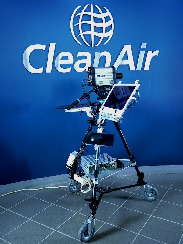
CleanAir has developed a method for remote velocity measurement using digital image correlation of images obtained with a high-speed infrared camera (shown in Figure 1). The method involves cross-correlating the pixel intensities in multiple images collected at various times to determine a velocity array that represents the velocity of the movement from one image to the next. This technique is generally known as particle image velocimetry (PIV). The simple step-by-step process of determining remote velocity using a high-speed infrared camera is as follows:
First, the high-speed infrared camera must be aimed at the plume. Then, the camera begins taking video/images at a predetermined frame rate. Finally, software analyzes the images using predetermined algorithms to determine the average velocity magnitude and direction of the plume.
While some plumes, like those created from a coal-fired power plant, are visible to the naked eye, other plumes may not involve the combustion of fossil fuels and are not readily visible. Therefore, we use a high-speed infrared camera in this process.
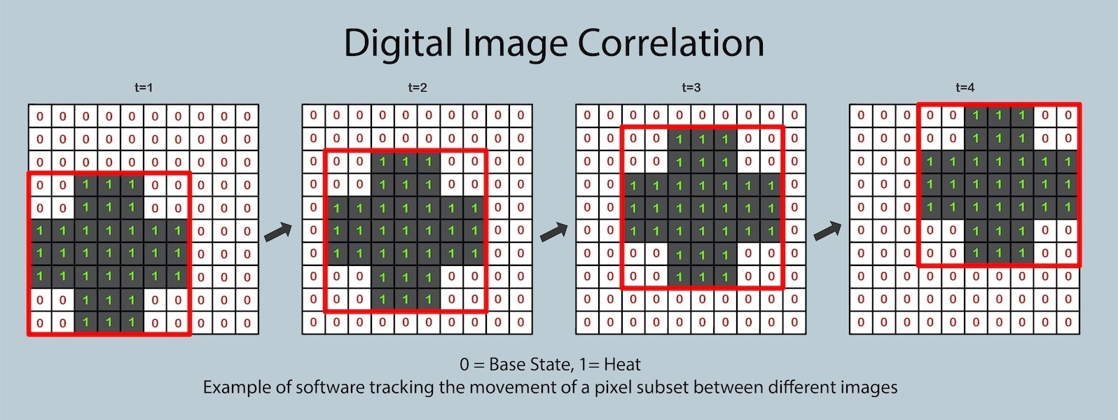
After the high-speed infrared camera has collected the images, these images must be preprocessed before being analyzed by the software. This includes selecting a region of interest within the plume to analyze and defining subsets within the region of interest. A subset of pixels within an image is selected such that the subset includes a non-repetitive, high-contrast range of intensity values. These subsets are what the software will analyze using digital image correlation to determine how far a grouping of pixels has moved from one time, t=1, to another, t=2, between images (as shown in Figure 2).


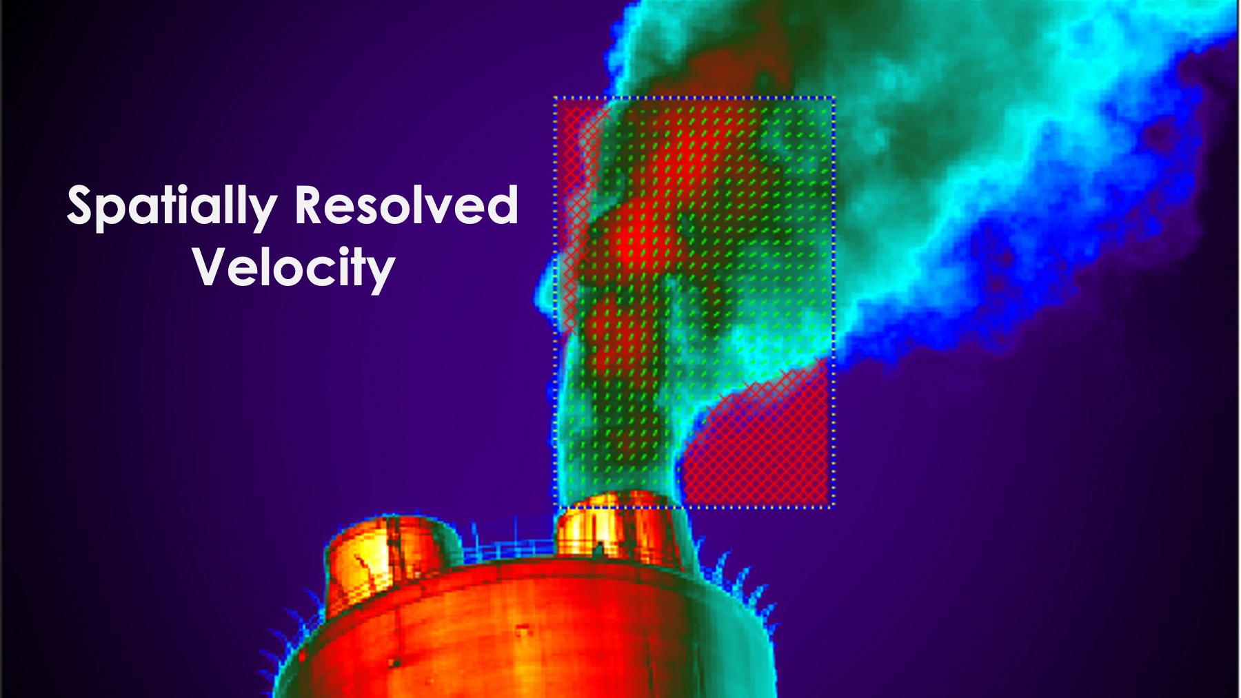
An array of displacements is then compiled that includes a displacement for each subset within the initial image providing values of pixel movement per image. As can be referenced in Figure 3, the software actually denotes areas with little to no subset movement with small red x’s and the remaining subsets are marked with small green arrows that represent both the magnitude and direction they have moved from t=1 to t=2. This represents spatially resolved velocity.
Large variations in subset velocities within a single pair of images can be reduced by taking high frame rate images and carefully defining the software algorithms and settings for each individual application of this method. Variation can also be reduced by including an algorithm to remove outliers. This allows determination of consistent and reliable velocity values.
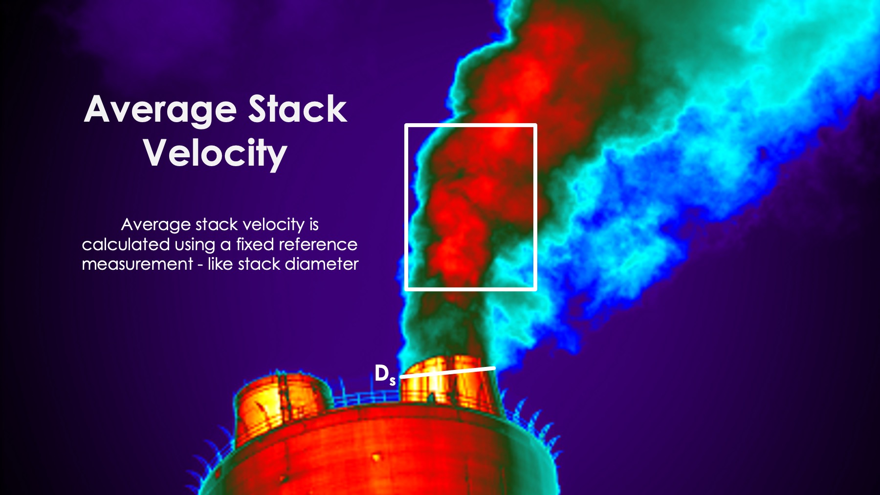
To provide a final quantitative measurement of plume average stack velocity, an actual known distance on the image must be identified, such as stack diameter (as shown in Figure 4). The pixels are then correlated to actual distances using the reference object with known dimensions within the image. Then, the camera frame rate is used to identify the time between images, which is subsequently combined with the actual distance to determine velocity. Using the average subset velocity over a specified area and over a specified number of image pairs helps determine the average velocity magnitude and direction for the plume which can be used in mass emissions calculations.
Field Trials
The PIV approach was tested in two field trials using a FLIR SC8313 High-Speed Infrared Camera. Field Trial 1 was performed at a coal-fired power plant and compared to reference measurements simultaneously obtained using EPA Method 2. Field Trial 2 was performed at an oil refinery and compared to reference measurements simultaneously obtained using EPA Method 2F. The results were as follows:


| Field Trial 1: Coal-Fired Power Plant | ft/s |
| FLIR SC8313 High-Speed Infrared Camera | 29.9 +/- 4.0 |
| Reference (Method 2) | 28.9 +/- 0.3 |
| Field Trial 2: Oil Refinery | ft/s |
| FLIR SC8313 High-Speed Infrared Camera | 74.8 +/- 12.8 |
| Reference (Method 2F) | 75.4 +/- 5.5 |
The remote camera velocity was within four percent of the values obtained using Method 2 at the coal-fired power plant and within one percent of the Method 2F values at the oil refinery. The close correlations between the two sets of measurements demonstrated proof of concept of this technology and method. The remote velocity measurements using the high-speed infrared camera did have larger standard deviations than those of the reference methods. However, the trade-off was that no stacks actually had to be climbed to obtain the camera-based measurements.
Summary
CleanAir’s PIV system measures post-emission, spatially-resolved gas plume velocities, which are required to determine mass emission rates. This type of system is less invasive than traditional stack testing methods or continuous emissions monitoring using an inline flow meter, and can be used to determine the velocity of plumes from sources that are not easily accessible, such as sources without a sampling port or mobile sources (e.g., ships and aircraft). Combined with other methods to remotely measure gas composition and particle concentration, mass emissions can be comfortably measured from the ground.


